
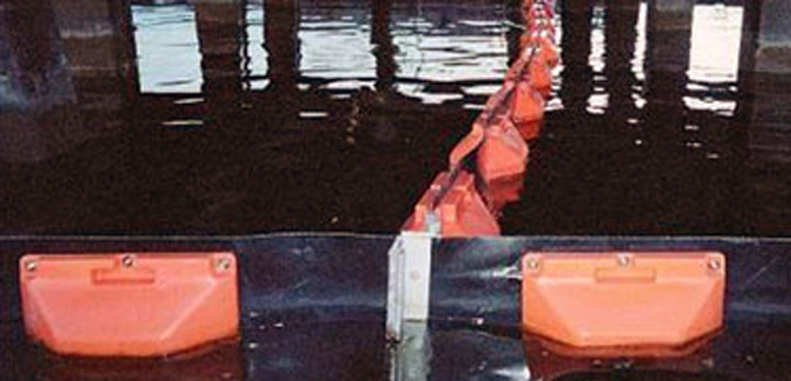
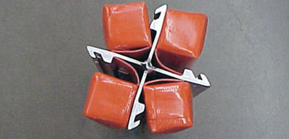
When you refer to floating a marine oil boom into 2, 3, or 4 directions, you are referring to specialized hardware called Multi-Way Boom Connectors (often just called splitters, Y-connectors, or cross-connectors by spill responders).
Instead of just laying an oil boom in a single, straight line, responders often need to branch the floating barrier in multiple directions to handle complex spills.
Here is how and why a floating boom is divided:
- Dividing into 2: Y-Connectors and T-Connectors
The most common way to divide an oil boom is into two diverging lines using a Y-Connector or T-Connector. - The Hardware: It is a rigid, floating aluminium hub with three connection tracks (one for the incoming main boom and two branching off).
Why divide into 2?
- River Forks: If oil is flowing down a river that splits around an island, a Y-connector is anchored at the fork. The main boom catches the oil, and the two branching booms deflect it away from both channels.
- Sweep Arms: When a ship is sweeping for oil, a T-connector is often used to attach a shorter “sweep arm” boom to the side of a main containment boom, creating a funnel that forces the oil directly into a mechanical skimmer.
Dividing into 3 or 4: Cross Connectors / Star Hubs
- To divide a boom array into 3 or 4 outward directions, responders use a Cross-Connector (a 4-way hub) or a custom multi-point attachment node.
Why divide into 3 or 4?
- Grid Systems and Holding Pens: In massive offshore spills, responders don’t just want one long line of boom (because if it breaks, all the oil escapes). Instead, they use multi-way connectors to build a “grid” or a series of connected rectangular “holding pens.”
- If one section of the grid fills up with oil or gets breached by a heavy wave, the adjacent pockets created by the 3-way or 4-way dividers will still contain the spill.
An ASTM “Z” Connector Divider is a specific type of multi-way hub built using the international standard “Z” profile (defined by the American Society for Testing and Materials, or ASTM).
When spill responders talk about standardisation, the ASTM Z connector is the most critical piece. Because oil spills often require equipment from multiple different agencies or countries to be combined, the connectors must be universal.
Here is how an ASTM Z divider works:
The “Z” Profile Standard
If you look at an ASTM connector from the top down, the extruded aluminium profile roughly resembles the letter “Z” (or an interlocking hook).
- When two sections of boom are brought together, the “Z” on one side slides vertically down into the reverse “Z” on the other side.
- Once they slide together, they form an almost completely flat, oil-tight, and highly secure joint.
- A drop-pin is then inserted through a pre-drilled hole in the centre of the interlocking hooks to prevent them from sliding vertically apart in the waves.
How the Divider is Built
To create a divider (like a Y-connector or T-connector) using this standard, manufacturers take a central floating hub or a rigid aluminium spine and weld multiple ASTM “Z” profiles onto it.
- For a Y-Connector: The hub will have one “Z” track facing backwards (to connect to the main incoming boom) and two “Z” tracks facing forward at an angle (to connect the two diverging booms).
- The Advantage: Because the divider uses the same ASTM Z profile as the standard end-to-end connections, responders don’t need any special adapter hoses, bolts, or tools. They slide the end of any standard ASTM Z boom directly into the divider, drop the pin, and the boom is successfully branched.
The end of the heavy fabric boom slides down vertically into one of the tracks on the Y, T, or Cross connector. A toggle pin is then dropped through the top to lock it in place, creating an instantly oil-tight seal in 2, 3, or 4 directions.